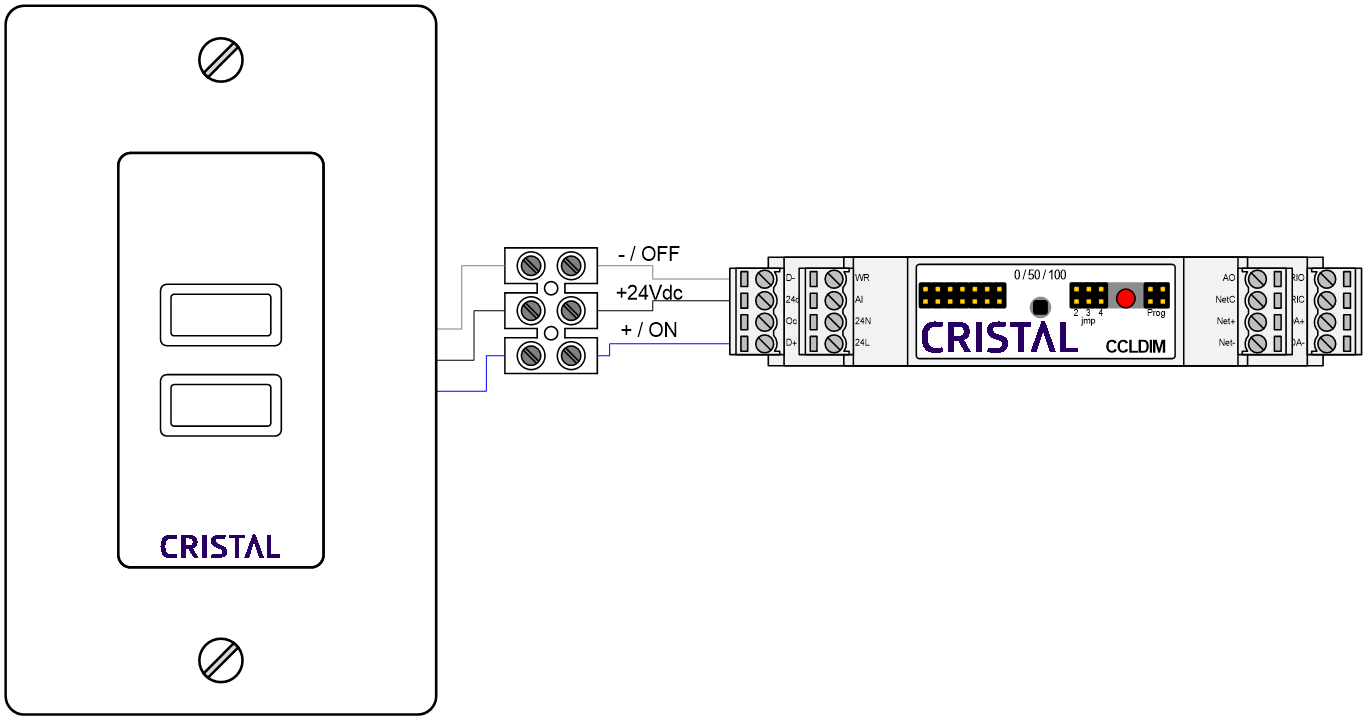
Installation

Terminal identification
 | WARNING: ELECTRICAL RISK Turn off the power supply before the beginning of the installation. Otherwise it can cause electrical shocks and damage the equipment. |
|---|
| Signal | Description |
|---|---|
| 24L | Positive (hot) power supply input terminal. |
| 24N | Negative (neutral) power supply input terminal. |
| Net + | RS-485 communication, positive terminal. |
| Net - | RS-485 communication, negative terminal. |
| DALI+ | DALI communication, positive terminal. |
| DALI- | DALI communication, negative terminal. |
| DI-1 Dim+ | Digital Input for button 1. |
| DI-2 Dim- | Digital Input for button 2. |
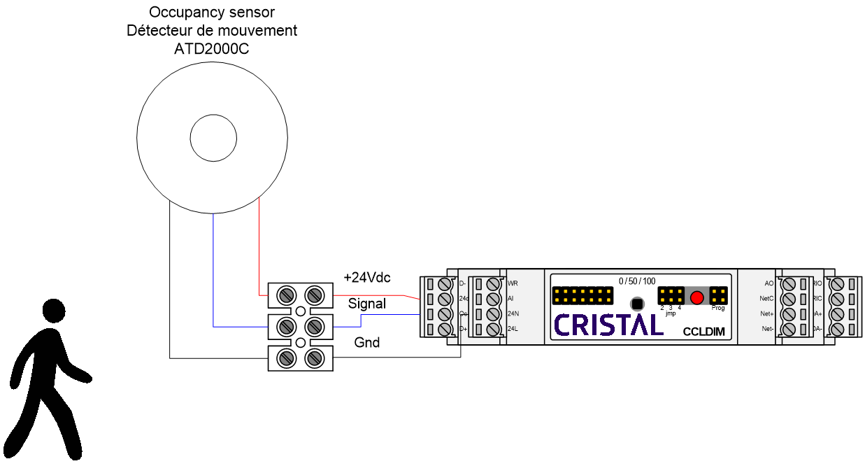
| DI-3 Occ | Digital Input for the occupancy sensor. |
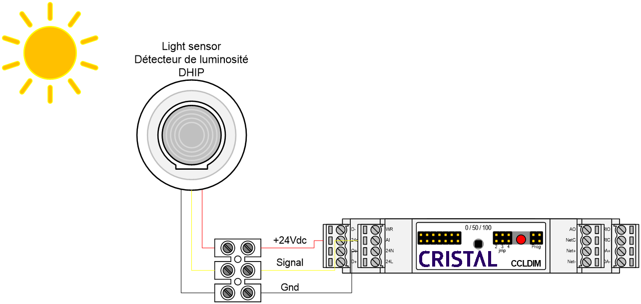
| 24Vdc Out | 24 Vdc power supply for the buttons, the motion sensor and the light sensor. |
| 0-10V Input | Analog Input for the light sensor or the potentiometer. |
| 0-10V Output | 0-10Vdc output. Connected to the 0-10 Vdc signal in ballasts and LED drivers. |
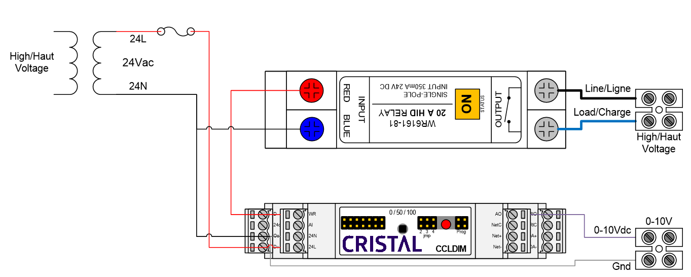
| Pulse Output | Pulse signal to control a WR-6161 latching relay. |
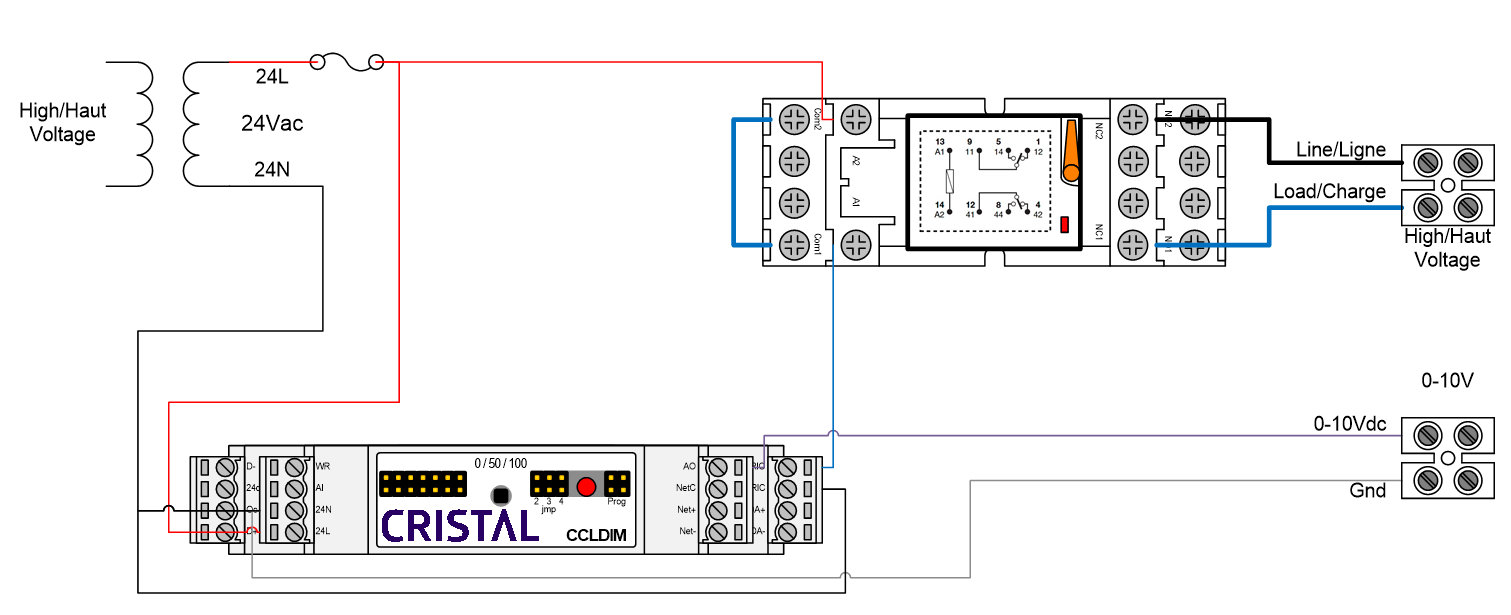
| RL Out | Traditional relay output (normally open). |
| Com | NO contact common terminal. |
Connections
WR-6161 relay wiring
Common relay wiring (RMIA Normally Closed)
Power pack wiring
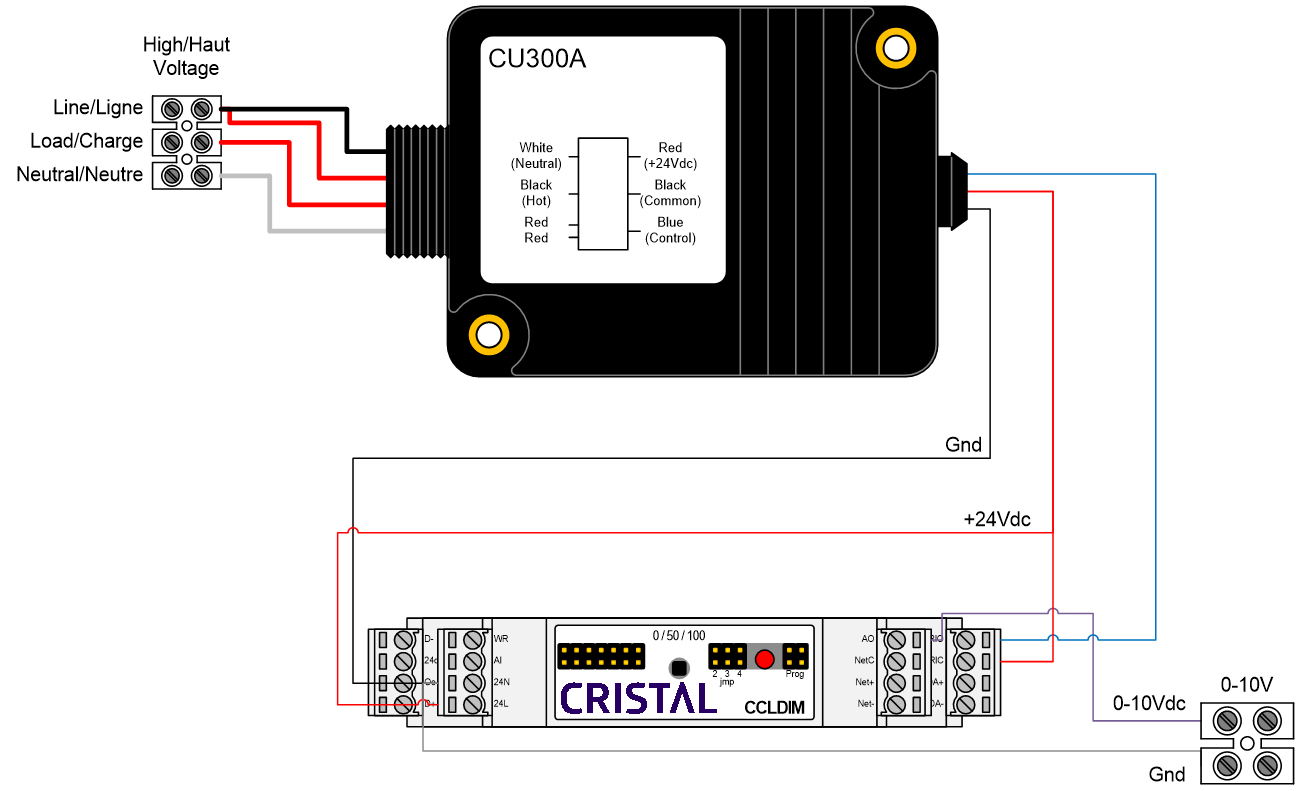
Note: the "Pulse Output" output is not functional with a 24Vdc power supply.
Wiring with an occupancy sensor
Wiring with a light sensor
Wiring with push buttons