Wiring
 | WARNING: ELECTRICAL RISK Turn off the power supply before the beginning of the installation. Otherwise, it can cause electrical shocks and damage the equipment. |
|---|
Terminal identification
Y1 Contact for first cooling stage.
Y2 Contact for second cooling stage.
Rc (Cooling hot supply) Connect to the hot on the secondary side of the transformer from your cooling unit.
0-10V out 0-10Vdc output for modulated heating stage.
W1 Triac output for first heating stage. This heating output is fed from the thermostat then its load reference must be the same as the one from the thermostat.
W2 Triac output for second heating stage.
Bus-A Positive terminal for RS-485 communication.
Bus-B Negative terminal for RS-485 communication.
0-10V In 0-10Vdc input.
Gnd Common terminal for analog 0-10Vdc signals.
AUX Relay contact for accessories or auxiliary heating.
G Fan Relay contact
COM Common hot signal for contacts AUX and G.
T Ext Two terminals for a remote temperature sensor with impedance of 10K at 25°C.
DI1-DI2 Digital inputs to detect a dry contact between this input and terminal COM2.
COM2 Common reference terminal for digital inputs 1 and 2.
24Vac_L Positive (hot) power supply terminal.
24Vac_N Negative (neutral) power supply terminal.
1 Transformer connections
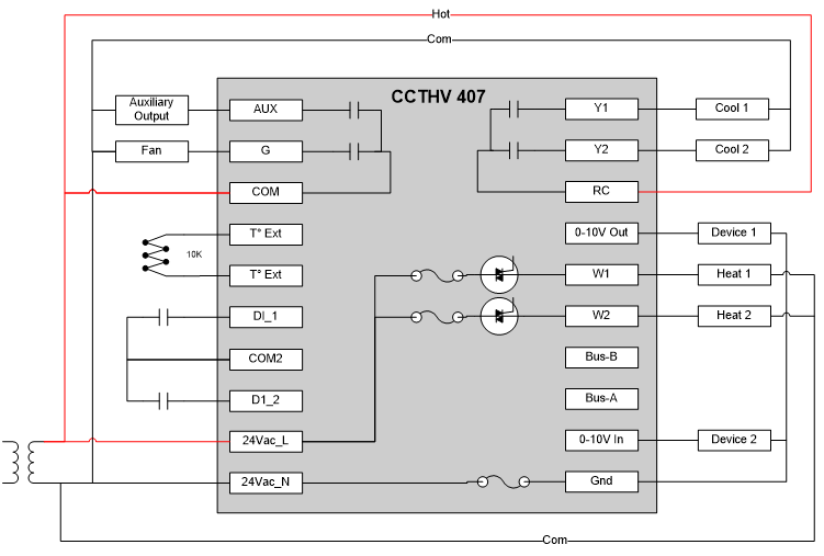
Figure 4 - 1 transformer wiring
2 Transformers connections
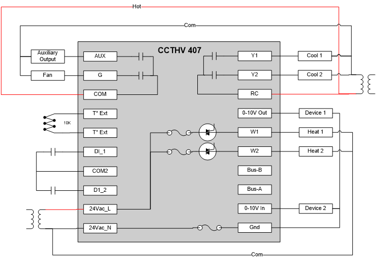
Figure 5 - 2 transformers wiring
3 Transformers connections
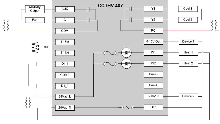
Figure 6 - 3 transformers wiring